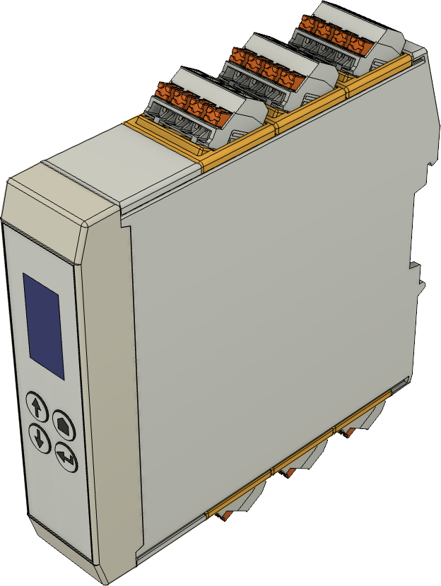
Six floating changeover contacts for 6 A at 250 V AC with rugged AgSnO₂ contacts. A contact monitor verifies the switching action.
| Outputs | 6× changeover (form C), floating |
| Switching capacity | 6 A at 250 V AC, max. 1500 VA resistive load |
| Contacts | AgSnO₂ |
| Contact monitor | per channel, 10 … 255 V AC / 8 … 350 V DC |
| Power supply | 24 V DC via the system bus, max. 2 W |
| Dimensions (H × W × D) | 100 × 25 × 115 mm (3.94 × 0.98 × 4.53 in) |
McNetic Ralf 1 switches loads and actuators via six floating relay outputs. Each channel is a changeover contact for 250 V AC / 6 A and brings the three contact terminals COM, NO and NC out to a plug-in connector. The module sits on the DIN rail together with Alpha 1, receives power and commands via the system bus and needs neither a power supply connection nor any configuration.
The changeover contacts switch 6 A at 250 V AC or 28 V DC, up to 1500 VA with a resistive load, and withstand making currents up to 10 A. The cadmium-free AgSnO₂ contacts are arc-resistant and resistant to welding, the right choice for contactors, valves, heaters and lamps. For reliable switching a minimum load of 100 mA at 12 V is recommended; for DC above 30 V the curve in the Contact load capacity section applies.
Driving a relay does not mean the load has actually been switched. That is why each channel has a fourth terminal, the monitor MON. Behind it is a sensing circuit that is powered directly from the switched potential, without an auxiliary supply, and detects whether the monitored contact is open or closed. The user decides by wiring what is monitored:
The firmware continuously compares the monitor with the expected relay state and reports deviations to the control program as a diagnostic event within 100 to 200 ms. The monitor works from 10 to 255 V AC or from 8 to 350 V DC and is protected against surges per IEC 61000-4-5 class 3.
Ralf 1 is available in the versions Basic, Standard and Plus. All three have the same six relays but differ in their further equipment. Standard adds the contact monitor, Plus additionally the mini display with four keys that shows the channel states and diagnostic values directly on the device.
The relay contacts are separated from the control electronics by reinforced insulation, the monitor inputs by basic insulation. The monitor inputs are protected against surges and can additionally minimise arcing at the contact, which extends the contact life. The hardware is designed for continuous operation up to 85 °C and avoids components prone to ageing.
Like every McNetic module, Ralf 1 checks itself at start-up: power supply, processor core, system bus and the relays. Defects are detected and reported before they show up in the installation.
| Dimensions (H × W × D) | 100 × 25 × 115 mm (3.94 × 0.98 × 4.53 in) |
| Mounting | DIN rail with integrated system bus connector |
| Connection | plug-in connectors with push-in spring terminals, max. 2.5 mm² (AWG 14) nominal cross-section |
| Weight | To be announced |
| Ingress protection | IP20 |
| Operating temperature (continuous) | −20 °C … +85 °C (−4 °F … +185 °F) |
| Number and type | 6× changeover (form C), floating, terminals COM, NO and NC per channel |
| Maximum switching voltage | 250 V AC / 350 V DC |
| Rated current | 6 A |
| Switching capacity AC | 6 A at 250 V AC, max. 1500 VA resistive load |
| Switching capacity DC | 6 A up to 28 V DC, 1 A up to 40 V DC, 0.15 A up to 300 V DC with resistive load (see curve) |
| Making current | max. 10 A for 4 s at 10 % duty cycle |
| Contact material | AgSnO₂, cadmium-free; arc-resistant and resistant to welding |
| Minimum contact load | 100 mA at 12 V (recommended) |
| Operate / release time | max. 12 ms / 5 ms |
| Switching frequency | max. 6 operations/min at rated load, 1200/min without load |
| Mechanical endurance | 10⁷ operations without load |
| Electrical endurance | approx. 6·10⁴ operations at 6 A / 250 V AC, approx. 1.2·10⁶ at 1 A (resistive load, curve); minimum per IEC 61810-1: 5·10³ at 6 A, cos φ = 1, 85 °C |
| Principle | read-back circuit per channel between the MON and COM terminals, in parallel with the monitored contact, powered from the switched voltage. |
| Operating range | 10 … 255 V AC, 8 … 350 V DC |
| Sensing current | max. 0.4 mA; flows through the connected load while the contact is open |
| Evaluation | comparison with the commanded relay state; deviations are reported as a diagnostic event after 100 … 200 ms |
| Application | wire jumper MON–NO or MON–NC monitors the module's own contact and the connection to the load; MON on the mirror contact of a contactor monitors its actual switching position (IEC 60947-4-1, Annex F) |
| Protection | surge immunity per IEC 61000-4-5 class 3, damps arcing at the contact |
| Contact – control electronics | reinforced insulation; test voltage 4000 V AC |
| Monitor – control electronics | basic insulation; test voltage 2000 V AC |
| Open contact | test voltage 1000 V AC |
| Channel – channel | reinforced insulation; test voltage 4000 V AC |
| Standards | relays per IEC 61810-1, VDE and UL certified; complete device: to be announced |
| Input | 24 V DC from the system bus (DIN rail) |
| Power consumption | max. 2 W with all relays energised |
| Protection | electronic fuse, current monitor |
| Display | mini colour display, 80 × 160 pixels, backlit |
| Functions | channel and monitor states as well as diagnostic values shown directly on the device |
The curves apply per contact with a resistive load. Inductive loads shorten the contact life and must be fitted with a suppressor in parallel with the load.
Values taken from the relay manufacturer’s data sheet, presentation by McNetic. The minimum values per IEC 61810-1 at 85 °C ambient temperature are listed in the technical data.
Ralf 1 comes in three versions with identical relay technology.
| Feature | Basic | Standard | Plus |
|---|---|---|---|
| 6 changeover contacts (form C), 6 A at 250 V AC / 28 V DC | ✓ | ✓ | ✓ |
| AgSnO₂ contacts, arc- and weld-resistant | ✓ | ✓ | ✓ |
| contact monitor per channel (MON terminal) | – | ✓ | ✓ |
| mini display and four keys | – | – | ✓ |
On Basic the MON terminal is not connected; the connector assignment is the same in all versions. The version is stored in the device and shown in the object model.
In both views the front with the display is at the top.
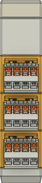
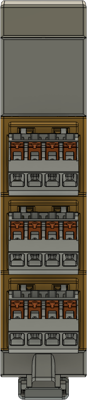
pin 1 optional wire jumper MON–NO or MON–NC: the monitor supervises the module’s own contact
Data sheet, manual and CAD data will follow with series production.
This module is expected to be available in our shop from Q1 2027.
 McNetic